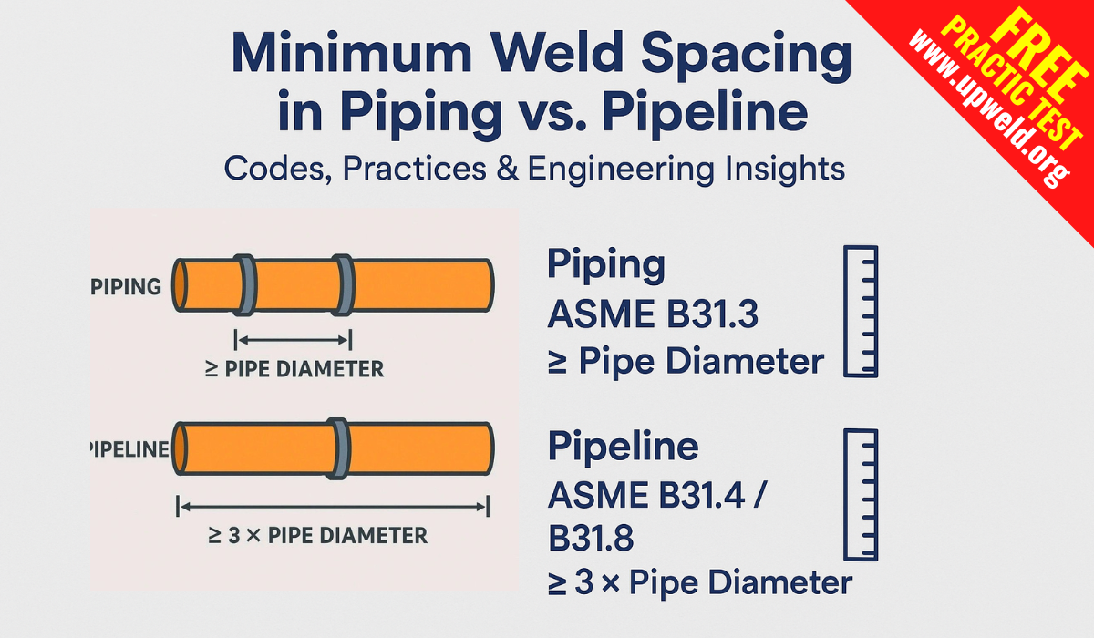
Minimum Weld Spacing in Piping vs Pipeline: Codes, Practices & Engineering Insights
When fabricating or designing piping systems, maintaining appropriate spacing between circumferential welds (girth welds) is crucial—not just for code compliance but also to ensure structural integrity, inspection ease, and long-term reliability.
1. What the Codes (Don’t) Actually Say
Piping – ASME B31.3 (Process Piping)
-
Contrary to common belief, ASME B31.3 does not specify a minimum spacing for circumferential welds (LinkedIn, General Technical knowledge).
-
Interpretations confirm: “There’s no Code requirement for the minimum distance between welds.” (General Technical knowledge).
-
Practical specifications from clients or engineering firms typically fill this gap, often suggesting values like 2 × wall thickness (2t) or 40 mm, whichever is smaller (Eng-Tips).
-
Some practices propose 4 × wall thickness or 1× pipe diameter, but never less than 1.5 in (≈38 mm) (Google Groups).
Takeaway: The code leaves it undefined—spacing is governed by engineering judgment or company-specific standards rather than mandated values.
Pipeline – ASME B31.4 / B31.8
-
No direct guidance found on minimum girth-weld spacing for pipelines in ASME B31.4/B31.8 code text (Gasplus).
-
A related note in B31.4 addresses sleeve spacing: “Distance between sleeves should be at least one pipe diameter”—but this pertains to sleeves, not welds (Gasplus).
-
Industry discussions mention a “rule-of-thumb” practice of 3 × pipe diameter or 3 inches between welds—but these are not code-based; they’re practical conventions (American Welding Society, Eng-Tips).
2. Why Spacing Matters: Beneath the Surface
Most blogs focus on code or rule-of-thumb spacing, but here’s what often gets overlooked:
Hidden Insight 1: HAZ Overlap & Cold Cracking
Even if spacing isn’t specified, overlapping heat-affected zones (HAZ) from closely placed welds can:
-
Increase susceptibility to cold cracking, especially in high-hardenability materials.
-
Compromise microstructure, leading to brittle zones that may not be evident during visual inspections.
Hidden Insight 2: Residual Stress Interaction
Adjacent welds can generate superimposed residual stresses that:
-
Amplify local stress concentrations.
-
Accelerate fatigue initiation under cyclic loading.
-
Reduce global fatigue life even in seemingly low-pressure systems.
Hidden Insight 3: Inspection Logistics & NDT Quality
-
While spacing is often justified for inspection access, narrow spacing (e.g., 10 mm) can hinder radiographic (RT) or ultrasonic (UT) scanning—scans may capture multiple HAZ simultaneously, reducing resolution or causing misinterpretation (Piping Stress).
-
Access for probes in automated inspection tools can be physically impeded in cramped weld arrangements.
Hidden Insight 4: Fabrication Realities & Field Constraints
-
In tight engineering layouts or in-field spool configurations, spacing flexibility becomes a negotiation point—clients often approve spacing reductions to maintain schedule, despite fabrication-wide recommendations like 3D spacing (American Welding Society).
Hidden Insight 5: Sleeve-Weld Interference in Pipelines
-
In B31.4 contexts where sleeves overlap or join welds, placing these closer than one diameter apart may interfere with pipeline integrity or post-install testing (Gasplus).
3. Data & Stats Snapshot
| Scenario | Typical Spacing Guideline | Source/Notes |
|---|---|---|
| ASME B31.3 (Process Piping) | No requirement; common practice: 2t or 40 mm minimum | (Eng-Tips) |
| Informal company-standard practice | Often 3 × D or 3 in (~75 mm) in piping layouts | (Eng-Tips) |
| Non-code discussion recommendations | 4 × t or 1 × D, with lower bound of 38 mm (1.5 in) | (Google Groups) |
| NDT recommendation (socket welds) | ≥ 10 mm (~0.4 in) spacing for inspection access | (Piping Stress) |
| Pipelines—sleeve spacing (not welds) | ≥ 1 × pipe diameter between sleeves | (Gasplus) |
4. Beyond the Basics: Engineering Considerations
-
Finite Element Analysis (FEA): In lieu of spacing standards, FEA can validate stress fields when weld spacing must be reduced. Crucial for high-pressure or cyclic pipelines.
-
Welding Procedure Qualification Records (PQR/WPS): Documenting HAZ profiles and heat input can quantify safe spacing for material-specific configurations.
-
Material Toughness & Environment: Low-temperature service or sour environments heighten the need for conservative weld spacing.
-
Regulatory vs. Contractual Authority: When code is silent (like ASME B31.3’s lack of minimum spacing), prioritize project specifications or client approvals, especially in petrochemical or process plant contexts.
Conclusion
-
ASME B31.3 (piping): No mandated minimum; industry relies on common practices (e.g., 2t/40 mm, 3D) filled by specs (LinkedIn, Eng-Tips, American Welding Society).
-
ASME B31.4/B31.8 (pipelines): No specific weld spacing; sleeve-spacing rules are separate and code-based (Gasplus).
-
Engineered spacing (>10 mm) is vital to avoid HAZ overlap, allow NDT, reduce residual stress interaction, and ensure fatigue integrity.
Read More: Here you can take a free practice test of the ASME B31.3 Exam with the Latest Questions
What Most Blogs Miss (and You Shouldn’t)
-
The literal absence of spacing requirements in codes like ASME B31.3.
-
How residual stresses from closely spaced welds degrade fatigue life—even when the HAZ seems acceptable.
-
The importance of inspection logistics, not just theoretical clearance.
-
Engineering remedies (FEA, PQRs) when spacing can’t meet informal rules.
-
Interplay between sleeve and weld proximity in pipelines—not just weld-to-weld concerns.
In summary, while many resources default to “spacing equals pipe diameter” or similar, the real world relies heavily on engineering judgment, site constraints, inspection capability, and project-specific specifications. When in doubt—or when practical constraints require alternate spacing—document the analysis through technical validation and client approval.
ASME B31.3 does not specify a minimum weld spacing for circumferential joints. However, industry practice recommends ≥2 × wall thickness (2t) or 40 mm, whichever is greater, to avoid HAZ overlap and allow NDT access.
ASME B31.4 and B31.8 do not explicitly define weld-to-weld spacing. Instead, industry practice suggests ≥3 × pipe diameter or ≥75 mm for field welds, especially because pipelines undergo bending and hydrotesting.
Proper spacing prevents overlapping heat-affected zones (HAZ), reduces residual stress interaction, ensures accurate NDT (UT/RT) inspections, and helps maintain weld quality under service conditions.
Yes, but only with engineering justification such as finite element analysis (FEA), weld procedure qualification records (PQRs), and client approval. Reduced spacing must still allow safe inspection and avoid structural risks.
Piping (B31.3): 2t or 40 mm (min)
Pipeline (B31.4/31.8): 3 × diameter or 75 mm (typical)
General rule of thumb: ≥1.5 in (38 mm) minimum spacing between welds.
Yes. Welds too close together can cause overlapping signals, making defect detection difficult. A spacing of at least 10 mm is usually required for effective NDT scanning.
Yes. Shop piping welds are usually guided by contractor specifications, while pipeline welds must account for field bending, hydrotesting, and sleeve installations—often requiring larger spacing.
Risks include:
Overlapping HAZ leading to brittle zones.
Increased residual stresses and cracking.
Poor NDT accuracy.
Reduced fatigue life under cyclic loading.
ASME B31.3 (Process Piping): No explicit requirement.
ASME B31.4 / B31.8 (Pipeline Codes): No direct requirement, but sleeve spacing is addressed.
Industry practices are documented in engineering forums (Eng-Tips, AWS), EPC specifications, and NDT guidelines.
Most EPC contractors and oil & gas companies define their own minimum weld spacing criteria in project specifications, often more conservative than code defaults, to ensure safety, NDT accessibility, and reliability.